In an attempt to gain some clarity on design decisions I will copy my ramblings from the Discord channel here.
[...] Original date: 2024-10-06
Any comments and suggestions are welcome as this is the first time I design an analog filter thing!
In short, I have been wanting to design a dual analog filter+vca which could be installed as an addon inside the Gills case and subjected to Ksolotian control.
I can’t make any promises so far if this design will work out and perform well (there be unknown challenges ahead such as CV generation, digital noise from Ksoloti, digital control etc.)
But here we go. After spending some time narrowing down on a certain filter type or topology, I am fairly certain we’ll go with a dual SSI2140 setup.
For the VCA part we’ll probably use the by now tried and tested SSI2164 in linear configuration.
I hope I can realize a multimode filter with selectable low pass, band pass, and high pass modes.
It actually seems doable to have the following modes, all digitally selectable using analog switch ICs:
Bypass. Gotta have a true bypass.
24 dB Lowpass. The classic venue shaker.
12 dB Lowpass. The workhorse. Perhaps not really necessary but the signal is there anyway and easy to tap.
24 dB and 12 dB bandpass. Not sure how useful it would be to have both, might skip one of them if it makes the hardware part easier.
24 dB and 12 dB highpass. Same like with bandpass, might skip one.
Notch seems to be possible but not sure how useful and how costly it would be.
Digital control has a few question marks. I’ve been going through several theoretical designs using different methods to create the CV for cutoff, resonance, and VCA gain, independently for both filters.
Creation of CV signals: we’ll have to multiplex CV signals for filter cutoff, filter resonance, amp vca, times two, resulting in six signals. Looking at old digitally controlled analog synth schematics, they seem to employ analog switch ICs followed by a cap and a buffer to sample and hold the individual CV values.
A polysynth could easily require a dozen or more CV signals per voice, all of which are multiplexed and sample-held. Our filter would only require six signals (two more “assignable” CV could be generated if there are unused pins and PCB space.)
Switching through signals at k-rate would result in a 2ms update rate per signal. (1/3000 Hz)*6
A further problem is that all six cv would be updated step by step, one every 333 us. This means that for a stereo filter, the delay between triggering the left and right vca, for example, might be up to 1ms, depending on in which order the CV signals are updated.
It would be possible to update the CV faster than k-rate by “abusing” the s-rate tab in our future filter control object, i.e. audio-rate at 48kHz, to update the filters.
I would want to keep these options available and set up the hardware design for max flexibility (also so that other MCUs could easily control the filter, not just Ksoloti)
How to generate the raw, pre-mux CV signal?
Option 1: PWM. Fast and easy?
There is (only) one free pin on Gills that is PWM capable: PA15. Tests showed that PA15 can comfortably create a PWM signal with up to 164 kHz frequency and a resolution of 512 steps, or 9 bits. The resolution could be doubled by halving the PWM frequency, but I assume 512 steps for filter control seems alright. Any higher resolution might perhaps be covered up inside the noise floor anyway.
Since we plan to update the filters at 3 kHz, or multiples of 3 kHz, the PWM frequency should be a multiple of 3 as well (to avoid parts of the PWM cycle be cut off during switching from one CV value to the next)
A multiple of 6 might be even better since we have six signals to cycle through.
Accordingly, a frequency of 144 kHz satisfies all multiple requirements, still giving a resolution of 512. (Actually a bit more, but the resolution should be a power of two for easier processing)
Or we could generate PWM at 72 kHz with a resolution of 1024 steps, or 10 bits, at the expense of higher noise and the need for more aggressive filtering of the PWM signals after multiplexing.
PWM will always need heavy filtering to create a clean enough DC voltage, which also means slower slew rates. With PWM, we may have to say goodbye to fast filter modulation and snappy envelopes.
I am currently inclined towards not using PWM, as not all MCUs could generate the particular timing and speeds I am assuming here. I would prefer for this board to be usable with any decent MCU or build system, so that it would also be not too hard to drop it inside an existing synth or effect box.
Option 2: Dedicated DAC IC, like MCP4x22, DAC8xx2, …
Advantages: dual DACs generate two signals simultaneously, so we would need only half the multiplexing effort, and both filters would be timed almost simultaneously. DAC signals are much cleaner and require less to no filtering (compared to PWM)
We need shift register multiplexing in any case for the filter mode and bypass switching, so adding a dedicated DAC would mean another data pin and separate clocks and whatnot to make all this work together at a certain timing.
SPI-based DACs are fast and efficient to program, however the recent ones require a 24-bit write per channel to update that channel’s CV value. Which then has to be switched and multiplexed to reach the respective filter control.
Which means additional bits and clocking on a separate shift register to set the mux address.
Option 3: Shift-register based “custom discrete” DAC
Okay “custom discrete DAC” is marketing speak for “DIY hacky DAC”. At least this is what I imagine a company would call their old and simple design to make it sound fancy.
But, at least for me, DIY is what Ksoloti is all about.
(I think I’ll be calling it DIYHackyDAC from now. Sounds fun)
Since we will already be using at least one serial-in, parallel-out shift register to set the filter modes and bypass, we might as well add a few registers to the chain and implement an R2R DAC.
Advantages: reasonably cheap, reasonably fast, fewer control pins required, all-in-one control interface, parts easily available, it is even breadboardable, lots of arduino-type code examples and libraries available, easily repairable in case a part of it breaks (which is unlikely, those shift registers have been around for decades doing their job)
Disadvantage: high parts count, takes up PCB space, specs might not be super hifi, requires external voltage reference (but so do many commercial DACs)
designing a dual DAC is also possible this way and we still save some CPU time, money and our sanity (?) writing up the control code (in form of independent axo objects, of course), while leaving the code accessible to users for hacking or improving it for their own purpose.
I am thinking a dual 10-bit DAC using 3 74HC595 shift registers and loads of 0.1% 0402 resistors.
We’ll have to see if this is doable on the available PCB area.
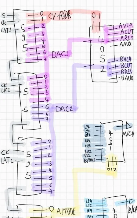
Dual 11-bit R2R DAC using 3 SIPO shift registers (pink and violet)
the two DAC signals are 4x multiplexed using a 4052 switch (driver and S/H circuits not shown) using the two LSB of the DAC shift reg sequence (red)
the fourth SIPO shift register retains the bit mask for filter mode (yellow/green) and bypass switching (brown). The shift reg has a separate latch pin so we can update and latch it independently from the (constantly changing) DAC bits.
the three mode bits for each filter control a 4051 analog switch, selecting response like LP, BP, HP etc.
the fourth bit for each filter controls master bypass (when this is on, the filter/vca is completely removed from the signal chain.
I wanted to have digital control over a gain/drive switch for a switchable filter overdrive, but it seems there will be no space for that. Planning to add physical little DIP switches to toggle drive (edit: it turns out there is a way, see below).
the interesting part is that the CV can drive external devices, essentially making this double as a Ksoloti to 8-CV interface.
TODO:
power requirements
is there a way to switch filter insertion: before Ksoloti’s audio in \ after Ksoloti’s audio out? Probably not feasible as this would require some rewiring of the audio inputs.
however a mono filter to effect chain seems possible:
Ksoloti left output (going thru filter A)-> Ksoloti left input.
Add effects to filtered audio → Ksoloti right output.
Yeah, no… there is not enough space inside Gills for a dual discrete DAC and dual filter board.
But there might be a way to design a single logic/dac/vcf/vca board and stack two of them. This also opens up new possibilities for a tiny single DAC chip on each board. Seems like those aren’t expensive at all.
Now we need to come up with an efficient way to push data bits to the DAC and the filter mode control register. Can’t think of an ideal way as this might mean we need to run two data lines and/or latches… or even separate clocks, for each single filter, to be able to set filter mode, then update and multiplex the CV values
Digital control now figured out, unless parts don’t perform as intended
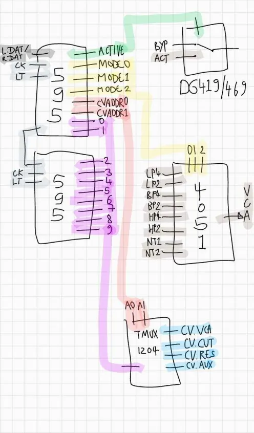
A single filter board (of up to two identical filter boards connected in parallel) is controlled using only three digital pins. One extra pin would control the second of two boards, so four pins are required for a dual setup:
LDATA, RDATA, CLOCK, LATCH
Included is a 10-bit DAC and four digital control pins that set filter mode and full bypass
The 10-bit DACs are multiplexed in parallel per filter board (thus the two DATA pins) but CLOCK and LATCH are shared for both boards. This improves the update rate and syncs CV timing of the two filters.
Now that the board only contains a single filter, there is an unused VCA circuit which I now call “AUX VCA” and route as a “voltage controlled filter drive” per default.
In short, this AUX VCA routes “more” of the line input to the filter as the VCA is opened. This way an adjustable overdrive can be had.
By cutting a few jumpers and soldering some wires to the respective pads, the AUX VCA can pass virtually anything, anywhere. I am thinking of cross filter signal routing (route filter 1 output per AUX VCA to filter 2 input because you always wanted an 8-pole highpass?)
Digital control should be fairly efficient: toggle CLOCK pin 16 times all while setting or clearing the DATA pins, then pull LATCH high to update.
Now the challenge is how to fit even a single board containing filter, vca, and control parts in a Gills-constrained board area, let alone two of them stacked.
Now thinking about extending the height of the whole Gills case by 5mm (and offer a case parts upgrade with the filter board), then use a full Core’s size of space under the Core itself for the filter board.
An advantage would be that non-Gills folks could simply stack the fiter board under a naked Core and filter away.
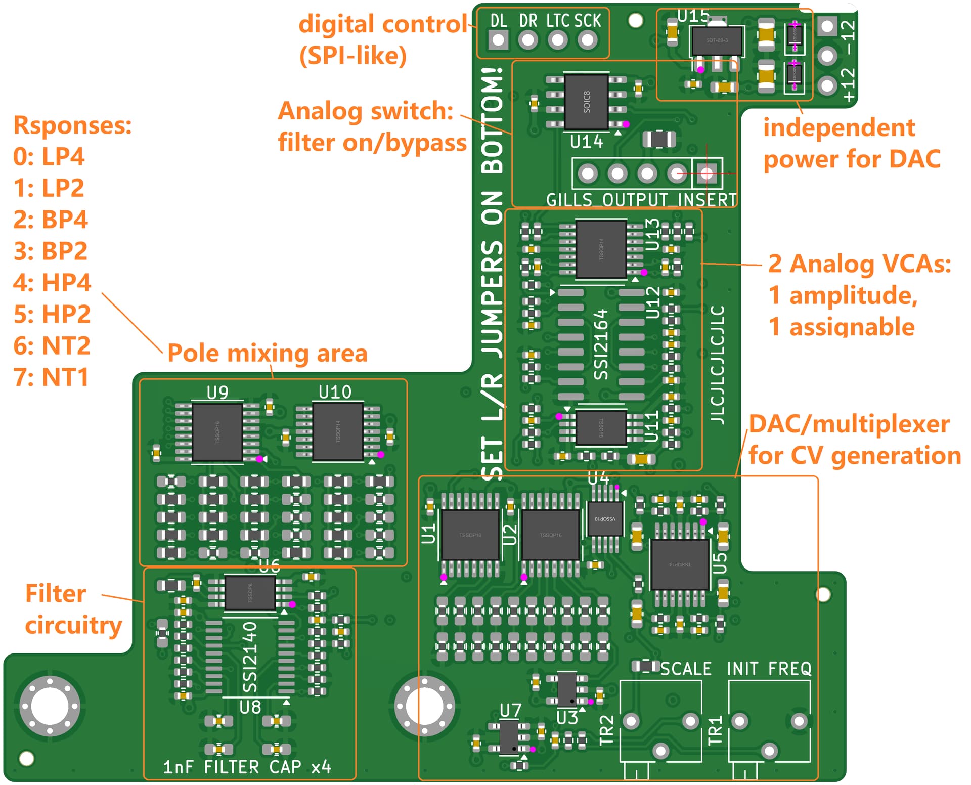
The weird shape is because it was meant to sit inside the Gills enclosure and plug directly into an insert header there. Even with this boomerang shape it probably won’t fit, but I need to get a physical object in front of me so I know what shape would!
The latest idea is to have the filter PCB made in the same size like the Ksoloti Core so it can be plugged on top of it, or under it, with the audio I/O handled somehow without too much wiring as well.
DAC/Demultiplexer generates CV for:
filter cutoff
filter resonance
amp vca gain
aux vca gain
The following controls are not CV per se, but digital:
filter mode
filter bypass
You select L or R channel via jumpers so you can stack two of these boards for true dual operation (with independent control)
At least that is the plan.
There are test points for all 4 CVs so you could wire them to jacks abd forward them to stuff. 0-5V, “only” 10bit resolution.
For the pole nerds out there, the filter taps and bipolar power are also brought out to test points so you could wire up an opamp and a few trimmers and mix your own response.
The more exotic responses seem overkill to me but you may just be after a very specific response, in which case go for it.
(I am writing this all assuming the prototype will work as intended!)
Good question, I was not able to find the ‘perfect’ DAC so far. Thinking about going with the DAC the Westlicht Performer is using - at 30 USD per chip! If you see anything cheaper that might work let me know!
that are recommended to replace that DAC8568ICPW which are in a smaller QFN footprint but they could be slotted into a socket to make soldering and replacement easier
I will look for different a different DAC but…
With a second look maybe smaller won’t make things easier. Maybe re-arranging this to fit on two smaller more streamlined boards that connect via ribbon cable and stack fitted into a deeper enclosure would allow for an easier fit beneath the ksoloti board as well as providing more space for a second 2140 for stereo ?